
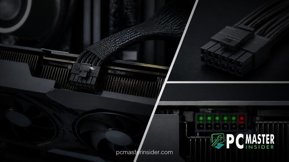
High-performance graphics cards demand clean, dense power delivery to handle heavy gaming, rendering, and AI workloads. However, the transition to high-wattage 16-pin power connections introduced significant thermal and structural challenges. Modern system builders frequently encounter loose terminal seats, severe cable bends, and unlatched headers that cause dangerous thermal hot spots. Learning how to install 12V-2x6 GPU power cable safely ensures long-term operational stability and protects expensive graphics hardware from catastrophic connector melting.
What You Will Learn in This 12V-2x6 Safety Guide
This tutorial provides a complete walkthrough for choosing, routing, installing, and validating 12V-2x6 high-power cables in modern desktop PCs. Here is an overview of what you will cover in this guide:
- The technical evolution from 12VHPWR to the revised 12V-2x6 hardware standard.
- Pre-installation checks for power supply unit (PSU) compatibility and cable integrity.
- Step-by-step physical installation instructions, proper cable routing, and bend distance rules.
- Thermal safety inspection methods and software monitoring tools to confirm connection stability.
Key Differences Between 12VHPWR and 12V-2x6 Connectors
The original 12VHPWR standard introduced alongside early PCIe 5.0 graphics cards presented reliability issues when cables were bent tightly near the plug or improperly inserted. In response, PCI-SIG released the revised PCIe CEM 5.1 standard and Intel updated its power guidelines with ATX 3.1 compliance, introducing the 12V-2x6 connector interface. Understanding how this socket design protects your hardware is the first step toward a safe build.
Sense Pin Changes and Power Delivery Safety
The 12V-2x6 revisions focus on mechanical fail-safes designed to prevent power flow if the cable is not fully seated into the socket:
- Recessed Sense Pins: The four sideband sense pins on the GPU socket are shortened by approximately 1.5mm compared to 12VHPWR. If the plug is not pushed all the way in, the sense pins fail to complete contact. The GPU detects this open circuit and refuses to draw high power, stopping thermal runaway before it starts.
- Extended Power Terminals: The twelve primary power terminals inside the socket are extended slightly to maximize contact surface area, lowering electrical contact resistance under heavy current loads.
- Mechanical Header Markings: Connectors compliant with the 12V-2x6 revision typically feature an H++ stamp on the housing, whereas older 12VHPWR hardware uses an H+ designation.
Pre-Installation Checks for Cables and Power Supplies
Before installing your hardware into the case, take time to verify that your power supply, cables, and graphics card match safe operating specifications.
Selecting ATX 3.1 PSUs and Compatible Adapters
To establish a clean power foundation, complete the following pre-installation checks:
- Verify Power Supply Standards: Ensure your power supply supports ATX 3.1 or ATX 3.0 standards. Native 12V-2x6 cables running directly from an ATX 3.1 power supply eliminate adapter clutter and reduce overall resistance across the line. Modern power supplies often feature built-in protective features, such as those seen on the Corsair HX1000i Shift Crystal PSU, which monitors terminal pin safety.
- Inspect Cable Sleeving and Contacts: Examine the 16-pin connector plug on both ends of the cable. Inspect the gold-plated pins inside the housing to confirm none are pushed back, misaligned, or corroded.
- Avoid Chain-Link Adapters: If your PSU lacks a native 16-pin output, use official multi-8-pin adapters provided by your GPU or PSU manufacturer. Never mix modular cables from different power supply brands, as pinout configurations vary and can cause permanent component damage.
Step-by-Step 12V-2x6 Installation and Cable Routing
Proper physical handling is the most crucial part of installing a high-power GPU cable. Follow these sequential instructions to install your 12V-2x6 cable safely.
1. Prepare the GPU Socket and Cable Alignment
Before plugging in the connector, clear working room inside your case so you can exert straight, even pressure on the plug.
- Power Off and Ground: Turn off the PSU rocker switch and disconnect the AC wall cord. Touch a grounded metal chassis section to discharge static electricity.
- Pre-Form the Cable: Gently pre-bend your 12V-2x6 cable to the desired direction before inserting it into the graphics card. Pre-forming the cable while unplugged prevents lever action from putting stress on the GPU power socket pins.
- Align Orientations: Orient the 16-pin plug so the top latch aligns with the latching clip on the GPU power header. Do not force the plug sideways or upside down.
2. Execute Full Latch Engagement and Flush Seating
Partial insertion is the primary cause of electrical hot spots and melted plastic housings. Achieving full engagement requires careful hand placement.
- Apply Firm, Direct Force: Place your thumbs directly behind the plug housing—not on the individual wire sleeves. Push the connector straight into the GPU socket until you hear an audible click from the retention latch.
- Perform a Visual Gap Check: Inspect the seam between the cable plug and the graphics card connector. There should be zero visible gap between the plastic plug face and the socket wall. If you see any part of the metal terminals or sense pin gap, push the connector inward again.
- Perform a Gentle Tug Test: Lightly pull back on the plastic housing (not the wires) to confirm that the clip firmly locks the cable into place.
3. Maintain Minimum Cable Bend Radius Near the Plug
Bending the 12V-2x6 cable too close to the connector housing pulls internal terminal pins out of alignment, creating uneven contact resistance across the 12V lines.
- Enforce the 35mm Straight Zone: Keep the cable completely straight for at least 35mm (approximately 1.4 inches) after it exits the rear of the plastic plug before beginning any curve.
- Avoid Horizontal Tension: Ensure the side panel of your PC case does not press firmly against the power cable. If your chassis is too narrow to allow a 35mm straight clearance, use a vertical GPU mounting bracket or a certified 90-degree 12V-2x6 cable.
- Secure Cable Ties Downstream: Apply zip ties or velcro straps only after the 35mm clearance zone to avoid pulling the harness sideways.
Verifying Power Connection Stability and Thermal Safety
Once installation is complete, system diagnostics must be run to confirm electrical stability under load.
1. Run Initial System Diagnostics and Voltage Monitoring
After closing your PC case and powering up the system, monitor internal sensor telemetry using diagnostic software:
- Boot into Windows: Power on the system and launch hardware telemetry utilities like HWInfo64 or GPU-Z.
- Locate GPU PCIe 12V Input Sensors: Find the sensor rows labeled GPU PCIe 12V Input Voltage or 12VHPWR Voltage. Healthy desktop power supplies should output between 11.8V and 12.2V under idle conditions.
- Check Component Health Metrics: Open Task Manager using Ctrl + Shift + Esc to confirm system stability and verify that operating memory is fully reported. If you need to monitor overall system resources, Microsoft continually refines hardware reporting, such as when Ctrl + Shift + Esc launches updated diagnostic views like the Windows 11 Task Manager total memory updates.
2. Conduct Stress Testing and Thermal Checks
Confirming safety requires subjecting the GPU to heavy graphics workloads while observing electrical stability.
- Execute a Synthetic Benchmark: Run a stress test tool such as 3DMark Time Spy or FurMark for 15 to 20 minutes.
- Observe Voltage Drop Under Load: Under full power draw, the 12V line voltage should remain stable and not drop below 11.4V. A sudden drop in line voltage indicates high resistance or loose pin contacts.
- Perform a Touch or Infrared Check: Safely feel the rear of the cable near the PSU or GPU socket after powering down, or use a thermal imaging camera while the system is running. The plug area should remain warm to the touch, but never uncomfortably hot or emitting plastic odors.
Best Practices and Safety Tips for 12V-2x6 Maintenance
Follow these quick best practices to ensure continuous safe operation for high-power PC builds:
- Avoid Repeated Mating Cycles: Standard 16-pin power connectors are rated for a finite number of plug/unplug cycles (typically 30 cycles). Avoid repeatedly removing the cable unless necessary.
- Never Force Narrow Side Panels: If your side glass panel presses against the cable plug, do not force it shut. Pressure from the side panel creates side-load stress on internal pins, increasing thermal risks.
- Use Cable Combs Wisely: Position cable combs well past the 35mm straight clearance area to maintain a neat aesthetic without tugging on individual wire sleeves.
- Re-check Connections After Transport: If you move or ship your desktop PC, open the side panel to re-verify that the 12V-2x6 cable remains fully flush and latched into place before turning the system back on.