
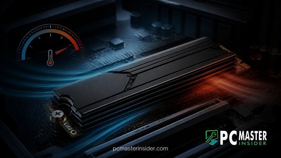
PCIe 5.0 NVMe SSDs represent the pinnacle of consumer storage performance, offering blisteringly fast transfer speeds that can exceed 14,000 MB/s. However, high throughput comes with a massive power footprint. Modern PCIe 5.0 controllers and NAND flash memory chips generate significant heat under heavy read and write workloads. When operational temperatures surpass safe thresholds—typically around 75°C to 80°C—the drive automatically reduces its clock speed to prevent permanent hardware damage. This protective behavior, known as thermal throttling, can drop your ultra-fast SSD's transfer speeds down to legacy PCIe 3.0 or SATA levels. Learning how to monitor drive thermals and implement proper cooling solutions is critical for maintaining maximum performance.
Overview of What You Will Learn
In this comprehensive guide, you will learn how to effectively diagnose and resolve thermal issues on high-speed M.2 drives. Specifically, we will cover:
- The mechanics of NVMe heat generation and why PCIe 5.0 drives require robust thermal management.
- How to configure real-time monitoring utilities to track composite and controller junction temperatures.
- Step-by-step methods to install active cooling heatsinks and high-conductivity thermal interface materials.
- Best practices for optimizing chassis airflow and motherboard M.2 slot selection.
- How to stress-test your storage setup to verify long-term stability under heavy workloads.
Understanding PCIe 5.0 SSD Operating Heat and Throttling
To effectively prevent PCIe 5.0 SSD thermal throttling, it helps to understand where the heat originates and how SSDs react to excess thermal load. Unlike older storage generations, flagship Gen 5 controllers manufactured on modern node processes pull upwards of 10 to 14 Watts of power under full load. Devices like the Goodram Master PCIe 5.0 SSD demonstrate the incredible speed potential of this generation, but sustained file transfers can rapidly overheat an uncooled drive within 30 to 60 seconds.
NVMe drives utilize distinct thermal zones. The SSD controller is the primary heat source and requires aggressive cooling to avoid critical throttling thresholds. Conversely, NAND flash memory functions most efficiently at moderate temperatures (around 40°C to 60°C), though extreme temperatures above 70°C will degrade retention and trigger throttling mechanism protocols. Passive motherboard heatspreaders designed for PCIe 4.0 drives often lack the surface area or active airflow required to keep modern Gen 5 controllers cool under continuous operation.
Step-by-Step Instructions to Reduce M.2 SSD Operating Temps
1. Set Up Hardware Temperature Monitoring
Before making physical adjustments, establish a baseline by monitoring your drive's idle and load thermal sensor readings.
- Download and install a trusted telemetry software tool such as HWiNFO64 or CrystalDiskInfo. Utilities like HWiNFO regularly expand diagnostic capabilities (much like how HWiNFO added per-chip VRAM monitoring for graphics cards) to give detailed sensor insight for individual storage controllers.
- Launch the application with administrative privileges. On Windows, press Win + X and select Terminal (Admin) or launch HWiNFO directly.
- Locate your PCIe 5.0 NVMe drive entry in the sensor list. Observe Drive Temperature 1 (typically the NAND flash array) and Drive Temperature 2 or Drive Temperature 3 (the main controller sensor).
- Take note of your idle temperatures; ideal idle levels should rest between 35°C and 50°C.
2. Install Active Heatsinks and High-Conductivity Thermal Pads
If your drive routinely exceeds 75°C during file transfers, upgrading from a flat passive aluminum plate to an active cooler is the most direct solution.
- Power down your system completely, switch off the power supply unit (PSU), and disconnect the main power cable.
- Open your PC case chassis and carefully remove your PCIe 5.0 M.2 SSD from its motherboard slot.
- Clean any leftover thermal residue off the controller and NAND packages using an isopropyl alcohol wipe (99% purity recommended).
- Apply high-conductivity thermal pads (typically rated at 12 W/mK or higher) across the top of the M.2 PCB. Ensure full coverage over both the central controller chip and the NAND flash modules.
- Attach a dedicated PCIe 5.0 active heatsink equipped with a micro-fan or dual heatpipes. Tighten the mounting screws evenly in a cross-pattern to establish uniform mounting pressure without flexing the circuit board.
- Connect the heatsink fan header to an available 4-pin PWM header on your motherboard (such as
CHA_FANorPUMP_FAN).
3. Optimize PC Case Airflow Around Motherboard M.2 Slots
Even the best heatsink requires ambient airflow to dissipate heat away from the cooling fins.
- Identify your motherboard's primary PCIe 5.0 M.2 slot. Check your motherboard manual to ensure the chosen slot is wired directly to the CPU's dedicated Gen 5 lanes rather than a shared chipset bus.
- Ensure your drive is not installed directly underneath the main exhaust heatsink of a hot graphics card, where ambient GPU heat can blanket the SSD.
- Reconfigure your front intake fans to deliver direct, unobstructed airflow across the motherboard's lower half. Adjust intake fan curves in the BIOS to maintain positive static pressure inside the PC chassis.
- Ensure internal cable routing does not block intake air paths directed toward the main storage slots.
Verifying Thermal Performance Under Sustained Storage Workloads
Once you have upgraded your cooling setup and optimized case ventilation, verify that your drive no longer experiences thermal throttling under sustained heavy stress.
- Launch your hardware telemetry tool (such as HWiNFO64) alongside a storage benchmarking utility like CrystalDiskMark or ATTO Disk Benchmark.
- Open Windows Task Manager using Ctrl + Shift + Esc and navigate to the Performance tab to observe drive utilization in real-time. Microsoft frequently refines diagnostic visibility across system components, including features like Task Manager hardware monitoring (similar to how they implemented per-process NPU monitoring in Windows 11).
- Configure your storage benchmark to perform a sustained sequence of 9-pass, 32 GiB sequential write tests to simulate demanding transfer conditions.
- Execute the benchmark while monitoring real-time thermals in HWiNFO64. Observe maximum peak temperatures on both the controller and flash memory sensors.
- Confirm that the controller temperature remains strictly below 70°C and that sequential transfer speeds stay flat throughout the duration of the test run without unexplainable dips.
Best Practices to Maintain SSD Health and Low Thermals
Keeping high-speed Gen 5 storage cool is an ongoing operational requirement. Incorporate these proactive maintenance habits into your system setup to prevent performance degradation over time:
- Update Motherboard BIOS and SSD Firmware Regularly: Drive manufacturers continuously release firmware updates that optimize power states, lower thermal output, and refine thermal throttling behavior without sacrificing peak performance.
- Maintain a Dust-Free Environment: Dust buildup on small M.2 active heatsink fins dramatically degrades heat dissipation efficiency. Clean your heatsink and case intake filters every three to six months using compressed air.
- Configure Fan Curves in BIOS: Tie the motherboard fan header powering your M.2 cooling fan to an aggressive PWM fan curve, ensuring fan speed ramps up as soon as drive temperature increases past 55°C.
- Avoid Stacking Thermal Interfaces: Never place stock motherboard heatsink thermal pads over pre-applied factory heatspreaders or labels unless specifically instructed by the manufacturer. Layering thermal interfaces increases thermal resistance and worsens heat retention.
- Ensure Proper Thermal Pad Thickness: Using thermal pads that are too thick can warp the thin M.2 PCB, while excessively thin pads leave air gaps over the controller chip, destroying thermal conductivity. Always check manufacturer tolerances before replacing thermal pads.